Learn Arduino with this plug and play circuit – no soldering or programming required!
What you’ll learn:
How to incorporate Arduino circuits into a Father’s day message.
Key takeaways:
There are two parts to building an Arduino circuit: the wiring and circuit components, and the programming.
Looking for an epic Father’s day project? This one will play the Star Wars theme song and display totally awful Star Wars Dad jokes as the song plays.
You can, of course, change the display text to anything you want, but if you want to tell Dad “YODA best” we have you covered in our initial program.
If you are just jumping into the world of Arduino and are a bit nervious, check out our other Arduino circuit that is motion activated and also plays Star Wars. That is a great first step towards this project as we will have similar wiring and code, except here we will add in an LCD screen.
Thanks to Tinkercad’s newest Arduino simulator addition you can work on learning how to make these circuits and program them even if your parts are in the mail.
Project Ingredients:Circuit starter kit (This one comes with a generic Arduino Uno board)PIR Motion detector (Some kits have it all, but they are pricier)
-OR-
Arduino Uno (you can reuse this board for many projects)PIR Motion detectorElectronics components kit16×2 LCD display (this is the only additional piece if you created our Star Wars musical circuit)
How to make a Star Wars themed LCD card with Arduino for Father’s day
Before we start, I just want to remind all the Moms out there who might be making this with their kids for Dad: You can do this. We are going to walk you through it just like we did with our beginner circuit.
Star Wars themed musical card that displays text on an LCD

1. Gather your supplies.
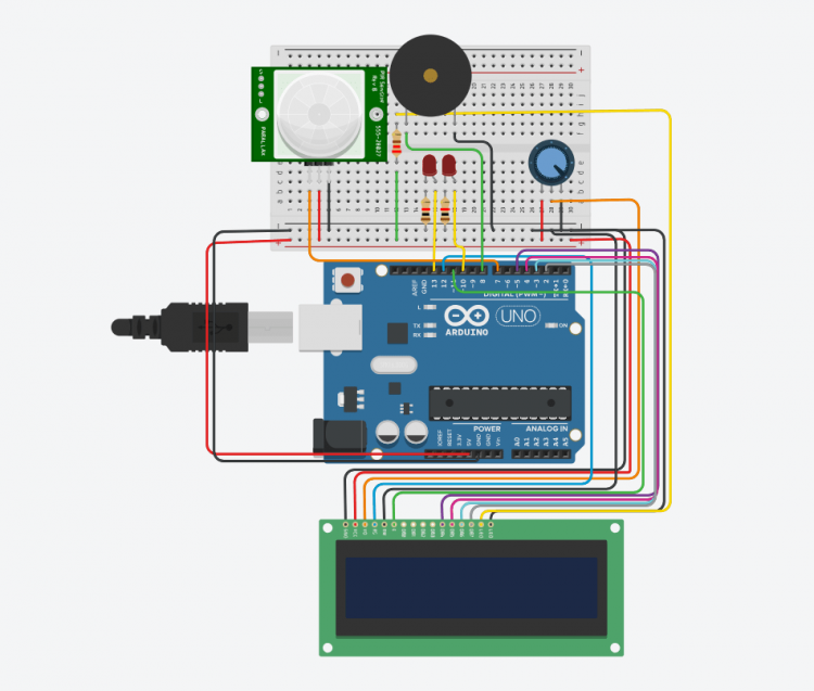
Like our earlier project, you will need your Arduino Uno, two LEDs, two resistors, a PIR detector (motion detector), a piezo buzzer, and jumper cables. You will also need a 16×2 LCD screen that has soldered connections which will allow this project to effectively become “plug and play”.
2. Build your circuit
Like before, you can do this before or after you push your program to the Arduino. Once the circuit is built you can connect the Arduino to your computer for power (or to push the code) and run it! If you want to be able to have the Arduino detached from the computer you will need a 9V DC cap to power it.
You can see this circuit execute the code in a simulation on Tinkercad. Once you have started the simulation you will need to click on the PIR detector (it looks like a large white ball). Doing so will show the zone that the PIR can detect motion in with a blue dot. Click on the blue dot to signal motion in that zone to the simulation.

Using Arduinos +5V and GND pins put power onto the bottom rails of your breadboard. The +5V red wire should connect to the +(red) bottom rail of the board, while the black ground connects to the black rail on the breadboard.

Add in the ability to detect motion with a PIR motion detector. PIR stands for Passive InfraRed that measures the IR light in its viewing angle. When a warm body (aka more infrared light) passes in front of the PIR it triggers the detector which then signals to the board that motion has been found.
Connect your PIR to the breadboard as shown, making sure to connect the ground (black) and power (red) pins into the breadboard rails and the signal pin into Arduino’s pin 7.

Once our PIR detects motion we want to play a tune. To do that we will need a Piezo buzzer. Like LEDs, piezo buzzers have a polarity or act like one-way streets. Find the small engraved ‘+’ sign on your piezo buzzer and connect it to pin 8 on your Arduino board. The other piezo buzzer pin will connect to the ground rail of the breadboard.

Place both LEDs into the breadboard as shown. Then connect the long leg of one to pin 13 on your Arduino through a 1kOhm resistor. The long leg of the other LED will also pass through a 1kOhm resistor and this time, into Arduino pin 10. This is effectively where our last, easier model, left off.

Your LCD display should come with a 10k potentiometer (or ‘pot’). A potentiometer is a variable resistor, by turning the screw in the top you can change the resistance going out. This will allow us to control the contrast on our LCD screen. A potentiometer has three pins. The outside pins go to ground and red respectively (it doesn’t matter which goes where since potentiometers are not polar like LEDs are). Hook these pins into the power and ground rails of your breadboard as shown.

Your LCD display has two pins marked ‘LED’. The one towards the outside (here the further right) is the cathode and needs to be wired into the common ground rail of the breadboard.

Connect the anode of the LCD LED (the second LED pin) through a 220 Ohm resistor and into the +5 rail of the breadboard. These two steps have powered your LEDs in the LCD screen.

Connect your data pins – these are DB4, DB5, DB6, and DB7. DB stands for Data Bus. These pins will accept the 8-bit data that the Arduino is sending and are wired into a small microcontroller on the LCD display itself. Here is the tricky part, on your Arduino:
DB4 needs to connect to pin 5 (technically labeled -5)DB5 needs to connect to pin 4DB6 needs to connect to pin 3 (technically labeled -3)DB7 needs to connect to pin 2

Enable the LCD by connecting the enable (E) pin of the LCD to pin 11 on the Arduino (technically labeled -11). This pin is either set high or low by the Arduino board. When it is low the LCD display is not doing anything. When it is set to high it is open to receiving data from the Arduino board (aka your program) to push to the screen).

Connect the R/W (read/write) pin to ground on the breadboard rail. Connecting this pin to ground sets your LCD display permanently to write mode, which is what we want since we are always pushing text we want the LCD to write to the screen.

Connect the RS (register select) pin on the LCD to pin 12 on your Arduino board. This will allow the Arduino board to send commands and information to the LCD.

A few steps up we plugged in a potentiometer to change the contrast of the LCD. However, we only plugged the two outside pins of the potentiometer into something (ground and +5V respectively). Connect the middle pin of the potentiometer to the V0 pin on your LCD which controls the LCD contrast.

Finally, power the LCD display. Connect VCC to the +5V rail on the breadboard and GND to the ground rail on the breadboard.

3. Program your Arduino
Plug your Arduino into your desktop computer and head over to Arduino’s code editor. If you have a Chromebook you can use CodeBender’s free 30-day trial to get the code pushed to your Arduino chip.
To program your Arduino Uno:
- In the Arduino IDE (the code editor) click on “New Sketch”
- Copy paste our code below into your “New Sketch”
- Click the checkmark in the upper left to verify the code
- Choose the Arduino Uno as your board and click push to board
The Code
Copy and paste the code below including the “//” in the beginning and the “}” in the end.
Learn about the code and the coding process here. Learn about the use of libraries in code below.
//Father’s Day motion activated Star Wars song.//Supplies: Arduino Uno, 2 LEDs, 2 1kOhm resistors, //piezo buzzer, PIR motion detector, jumper wires//www.rosieresearch.com
// include the library code (this is the library for the LCD display):#include <LiquidCrystal.h>
//TEXT AND FORMATTING//Text changes throughout the music, enter the text you//want displayed below.//Each line has 16 characters, to center you must count//the characters and add necessary spaces before the text.
//Type initial text (each line up to 16 char)char myTEXT1a[]=” Happy Father’s”;char myTEXT1b[]=” day!”;
//Type text 2 (each line up to 16 char)char myTEXT2a[]=”YODA best dad in”;char myTEXT2b[]=”the universe!”;
//Type text 3 (each line up to 16 char)char myTEXT3a[]=” Your day it is”;char myTEXT3b[]=” “;
//Type text 4 (each line up to 16 char)char myTEXT4a[]=” Celebrate”;char myTEXT4b[]=” we must”;
//Type text 5 – Final text (each line up to 16 char)char myTEXT5a[]=” Love you”;char myTEXT5b[]=” we do”;
//DEFINE VARIABLES
//Create musical notesconst int c = 261;const int d = 294;const int e = 329;const int f = 349;const int g = 391;const int gS = 415;const int a = 440;const int aS = 455;const int b = 466;const int cH = 523;const int cSH = 554;const int dH = 587;const int dSH = 622;const int eH = 659;const int fH = 698;const int fSH = 740;const int gH = 784;const int gSH = 830;const int aH = 880; //define pin connectionsconst int buzzerPin = 8;const int ledPin1 = 10;const int ledPin2 = 13;const int pir=7;LiquidCrystal lcd(12, 11, 5, 4, 3, 2);
//define countersint counter = 0;
// the setup routine runs once when you press reset:void setup() { // setup pin modes pinMode(ledPin2, OUTPUT); pinMode(ledPin1, OUTPUT); pinMode(buzzerPin, OUTPUT); pinMode(pir, INPUT_PULLUP); }
// the loop routine runs over and over again forever:void loop() { //Check for motion if(digitalRead(pir)==HIGH) { //if motion is detected, setup LCD lcd.begin(16, 2);
//print 1st message as defined above in ‘mytext1a/b’ lcd.print(myTEXT1a); lcd.setCursor(0, 1); lcd.print(myTEXT1b);
// Play the song firstSection(); //print 2nd message lcd.clear(); lcd.setCursor(0, 0); lcd.print(myTEXT2a); lcd.setCursor(0, 1); lcd.print(myTEXT2b);
//Play second section secondSection(); //print 3rd message lcd.clear(); lcd.setCursor(0, 0); lcd.print(myTEXT3a); lcd.setCursor(0, 1); lcd.print(myTEXT3b); //Variant 1 beep(f, 250); beep(gS, 500); beep(f, 350); beep(a, 125); beep(cH, 500); beep(a, 375); beep(cH, 125); beep(eH, 650); //print 4th message lcd.clear(); lcd.setCursor(0, 0); lcd.print(myTEXT4a); lcd.setCursor(0, 1); lcd.print(myTEXT4b); delay(500); //Repeat second section secondSection(); //Variant 2 beep(f, 250); beep(gS, 500); beep(f, 375); beep(cH, 125); beep(a, 500); beep(f, 375); beep(cH, 125); beep(a, 650); //print 5th message lcd.clear(); lcd.setCursor(0, 0); lcd.print(myTEXT5a); lcd.setCursor(0, 1); lcd.print(myTEXT5b); delay(650); } else { digitalWrite(ledPin2, LOW); // turn the LED off by making the voltage LOW delay(200); } }
void beep(int note, int duration){ //Play tone on buzzerPin tone(buzzerPin, note, duration); //Play different LED depending on value of ‘counter’ if(counter % 2 == 0) { digitalWrite(ledPin1, HIGH); delay(duration); digitalWrite(ledPin1, LOW); }else { digitalWrite(ledPin2, HIGH); delay(duration); digitalWrite(ledPin2, LOW); } //Stop tone on buzzerPin noTone(buzzerPin); delay(50); //Increment counter counter++;} void firstSection(){ beep(a, 500); beep(a, 500); beep(a, 500); beep(f, 350); beep(cH, 150); beep(a, 500); beep(f, 350); beep(cH, 150); beep(a, 650); delay(500); beep(eH, 500); beep(eH, 500); beep(eH, 500); beep(fH, 350); beep(cH, 150); beep(gS, 500); beep(f, 350); beep(cH, 150); beep(a, 650); delay(500);}
void secondSection(){ beep(aH, 500); beep(a, 300); beep(a, 150); beep(aH, 500); beep(gSH, 325); beep(gH, 175); beep(fSH, 125); beep(fH, 125); beep(fSH, 250); delay(325); beep(aS, 250); beep(dSH, 500); beep(dH, 325); beep(cSH, 175); beep(cH, 125); beep(b, 125); beep(cH, 250); delay(350);}
Learning the code: Understanding libraries
There are a few key differences in the code of this program versus the program that does not display text on a screen.
First, we defined a bunch of char myTEXT lines. These allows us to easily change the text displayed on each line of the screen.
The second big change is the inclusion of a library as seen in the line: #include <LiquidCrystal.h>
What are libraries, and why do we use them in programming? Think of libraries as a chunk of code that you won’t need to write. If you want to use an LCD screen you don’t need to write all of the code for how the microcontroller on the LCD talks to the Arduino board. Nor do you need to think about how the data, in the form of high and low voltages, will be written in letters, how those letters will form, how they will go from left to right on the screen.
It’s not that the computer actually knows how to use an LCD screen. It doesn’t.
It’s that someone before us put in a ton of time and effort into teaching the computer how to speak LCD. By including the library we are effectively teaching our computer (our Arduino) how to talk to an LCD.
There are tons of libraries out there. Some help you play songs, some automatically download data from the internet, others know how to measure and report the measurement with precision.
We only include the libraries we need because otherwise, our computer’s brain wouldn’t have enough storage (or memory) to keep up with everything.
So imagine a library as a huge book of code that is already written for you, which you can use in your code if you need.